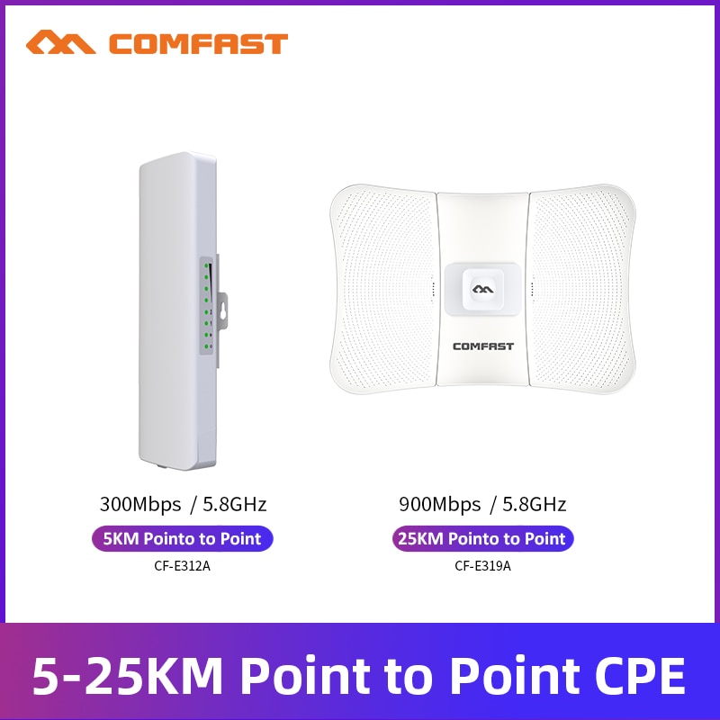
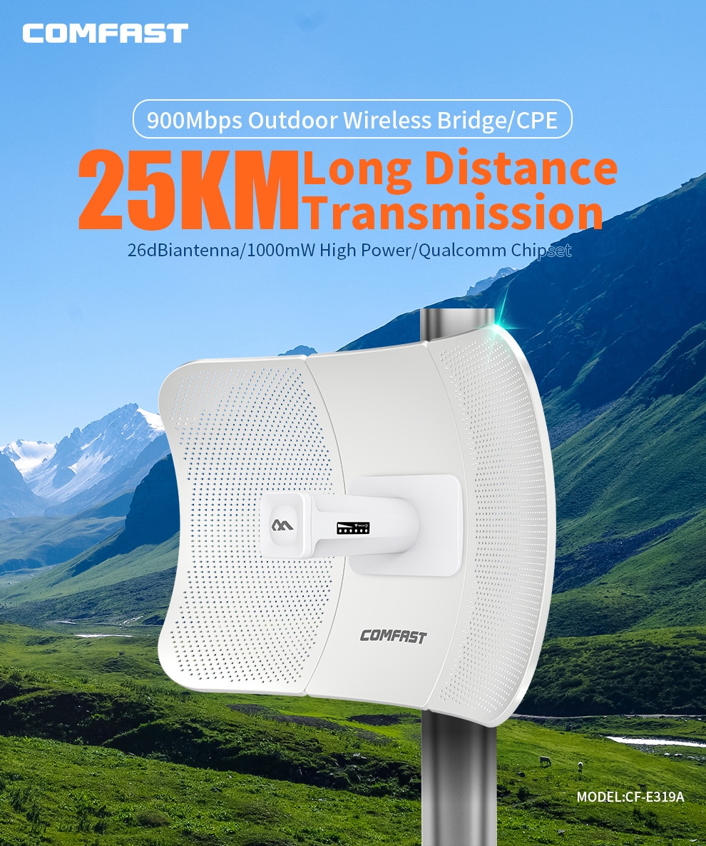
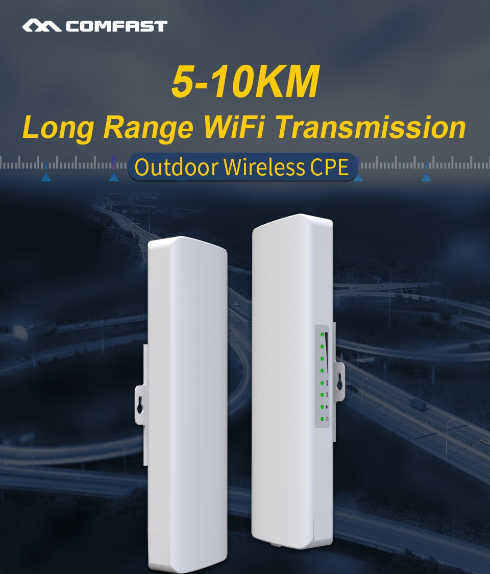
5-25KM Long Distance Transmission 5GHz Outdoor Wireless Bridge Wi-Fi CPE Access Point Long Distance Wifi Signal Amplifier Antenna Nanostation Extender AP
CF-E319A Specifications:
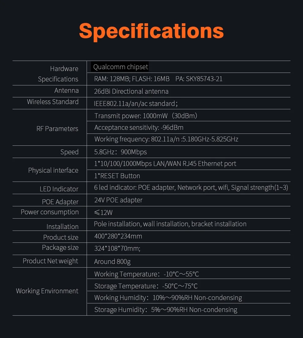
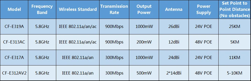
Antenna: 26dBi high-gain directional butterfly shape antenna
Wireless Standard: IEEE802.11a/an
Output Power: 1000mW(30dBm)
Receiving Sensitivity: -96dBm
Frequency: 802.11a/n: 5.180GHz-5.825GHz
Physical Ports: 1*10/100/1000Mbps LAN/WAN RJ45 Ethernet
Package included:
1/2* CPE
1/2* Poe Adapter
1/2* Quick install guide
1/2* Power cable
2/4* Stainless Steel Ring
Note: 25km means 2pcs CPE set point to point as wifi bridge(No obstacles)

 The Measured Transmission Reaches 25KM Kilometers
Qualcomm chipset, together with PA can improve the transmission power.The measured transmission distance in an open environment is about 25KM(60 dBmTransmit Power; 25 KMLong Transmission; PA+LNAHigh Power)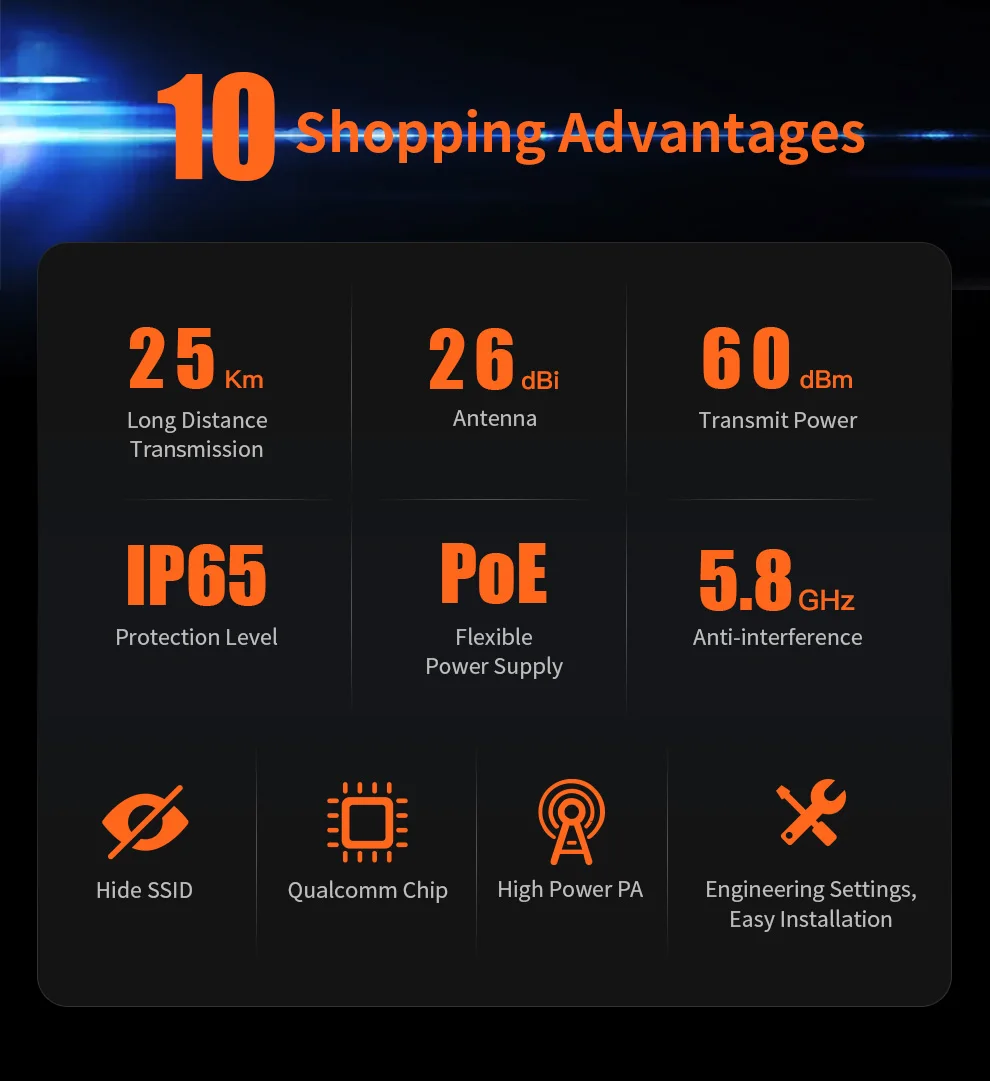 900Mbps HD Transmission
CF-E319A supports 900Mbps wireless rate, 900M broadband,and transmits 20 high-definition cameras without delay.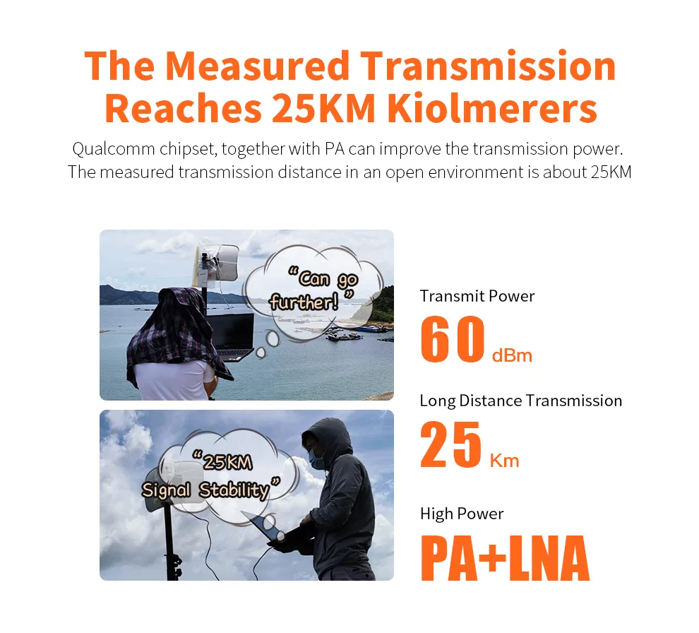 Outdoor IP65 Rating Provides The Ability to Handle Different Kinds Of Rugged surroundings
Lightning protection/ Waterproof/ Antifreeze/ Dust Proof/ High Temperature Resistance/ Anti-oxidation Butterfly Shape High Power Antenna
Using 26dBi high-gain directional butterfly shape antenna exclude interference, not only the signal is strong, but also suitable for long-distance connections
Metal paraboloid, sensitive to receiving; 2*2 MIMO, improved the transmission efficiency 5.8GHz Effective Anti-interference
There are too many devices in the 2.4GHz band and cause serious interference, CF-E319A work at 5.8GHz, the interference is less and works more stable 10 Advantages
25Km Long Distance Transmission
26dBi Antenna
60 dBm Transmit Power
IP65 Protection Level
PoE Flexible Power supply
5.8GHz Anti-interference
Hide SSID
Qualcomm Chip
High Power PA
Engineering Settings, Easy Installation Industrial design
Function 1: Wind resistance antenna reflector
The reverse design of the through-hole antenna is adopted to effectively reduce wind resistance andresist stormy weather, and the product adaptability to the environment is greatly improved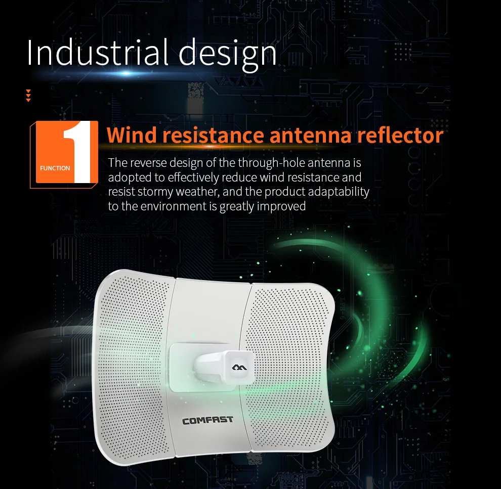 Function 2: Led indicator is easy to adjust
Equipped with signal status indicator, which is convenient for users to adjust the angle of the device, and the signal status is clear at a glance
Three lights are on, the signal is strongest
–WiFi indicator flashing, Wireless data transmission
–WAN/LAN indicator flashing, Network transmission data
–Power light is on, the device is connected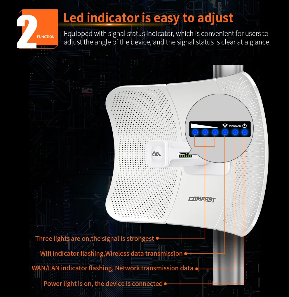 Function 3: The level design
The level design can help users quickly judge whether theinstallation angle is accurate, and it is clear at a glance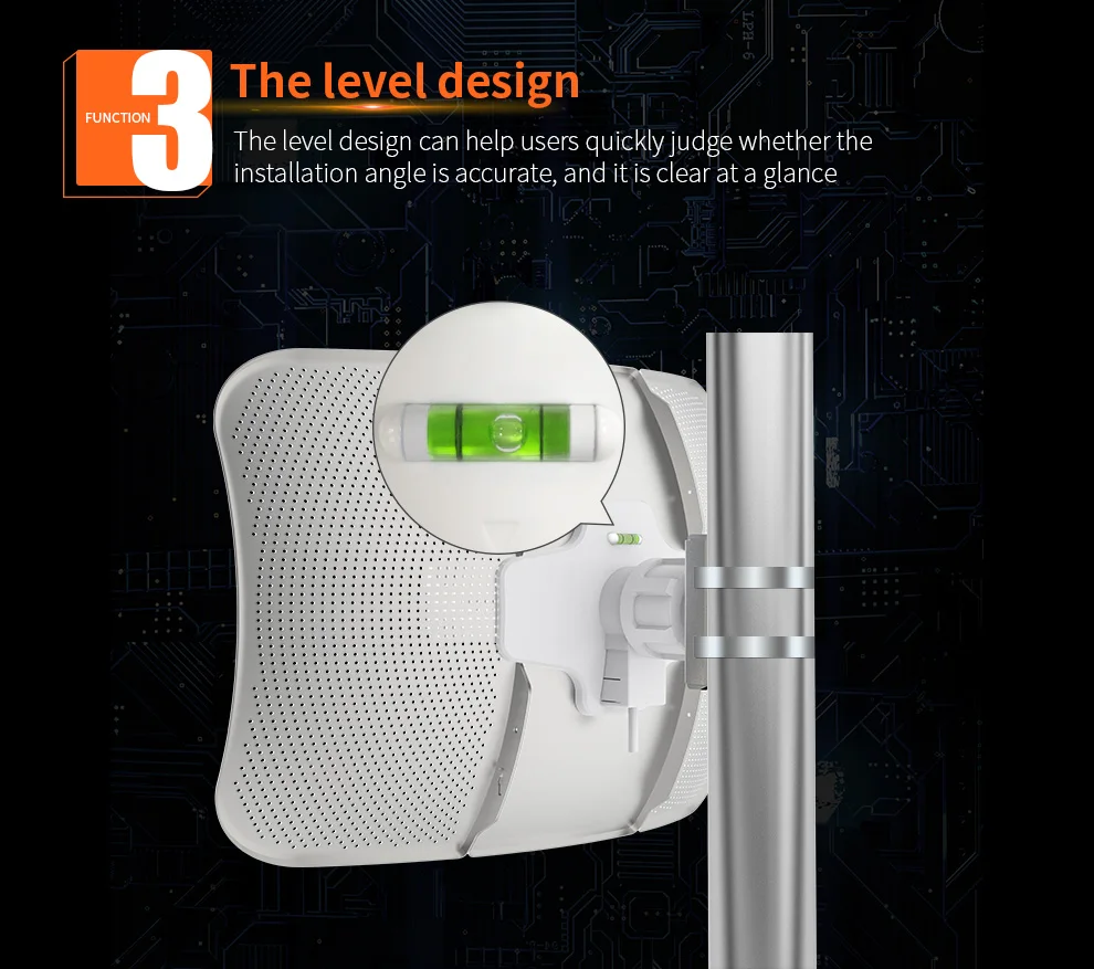 Function 4: Installation clip, flexible rotation
The innovative design of the installation clip, the bridge can berotated and adjusted at any angle, which greatly enhances theflexible application ofthe project POE Power Supply
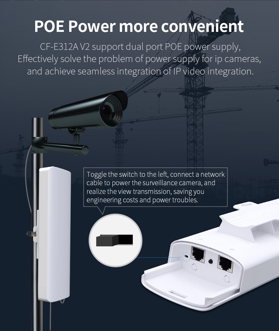
CF-E319A support POE power supply,It can support 100-meter long network cable for power supply and data transmission at the same time. It ismore convenient to get electricity for outdoor projects, free from the shackles of power supply problems. Makes project easier.
 Hide SSID, Refuse to Backup The Network
The wireless bridge supports SSID broadcast hiding, which can easily solve the troubles of the backup network and ensure the stability of the project Powerful Software Management
The wireless bridge software has a scientific and humanized operation GUl, simple user settings, rich functions, and strong practicability Monitoring Applicable Scenarios
Farming monitoring/ Forest monitoring/ Driving school monitoring/ Road monitoring/ Scenic spot monitoring/ Site monitoring
Network Application Scenarios
Cell network transmission/ Scenic network transmission/ Network transmission in remote areas Schematic Diagram of Wireless Bridge Connection
Scene 1: Point to point connection
Multiple camera connection: Connect the camera to the switch,then connect to the comfast bridge, and transmit data through the one-to-one bridge Scene 2: Multi point to Multi point connection
If the cameras are far apart, you can configure a pair of bridges for each camera, and the monitoring center uses a switch to connect the AP terminals together and then connect to the hard disk video recorder Scene 3: Point to Multi point connection
lf the angle between the location of the camera and the monitoring center is less than 120 degrees, point-to-multipoint can be consideredto reduce the cost of the transmitter bridge, but the prerequisites need to meet the angle and broadband requirements Scene 4: Build a local area network
A network bridge can be used to build a local area network for data transmission when there is no external network Scene 5: Wireless Repeater
lf the distance between the two places AB is very long and the data transmission does not reach, a relay forwarding point C can beestablished in an unobstructed place between the two points AB, and the point C receives the data from point A and then relays it to point B to achieve normal wireless data transmission lnstallation Steps
①Connect the three antenna sets
②lnsert the base on the antenna and fix it with two screws
③Insert the shell +cover into the reflector
④Screw the bracket +nut+device clockwise on the base device
⑤Pull out the back waterproof cover, insert the network cable into the port, and push back the cover
⑥Open the stainless steel tie through the 4 slots, on the bracket and fix the device onto the pole. Package Content
PS: Measured manually with slight deviation


Reviews
There are no reviews yet.